E2 Installation Process
This following diagram illustrates the 1:200 (0.5%) Built-in-Fall is in the wall of the Channel
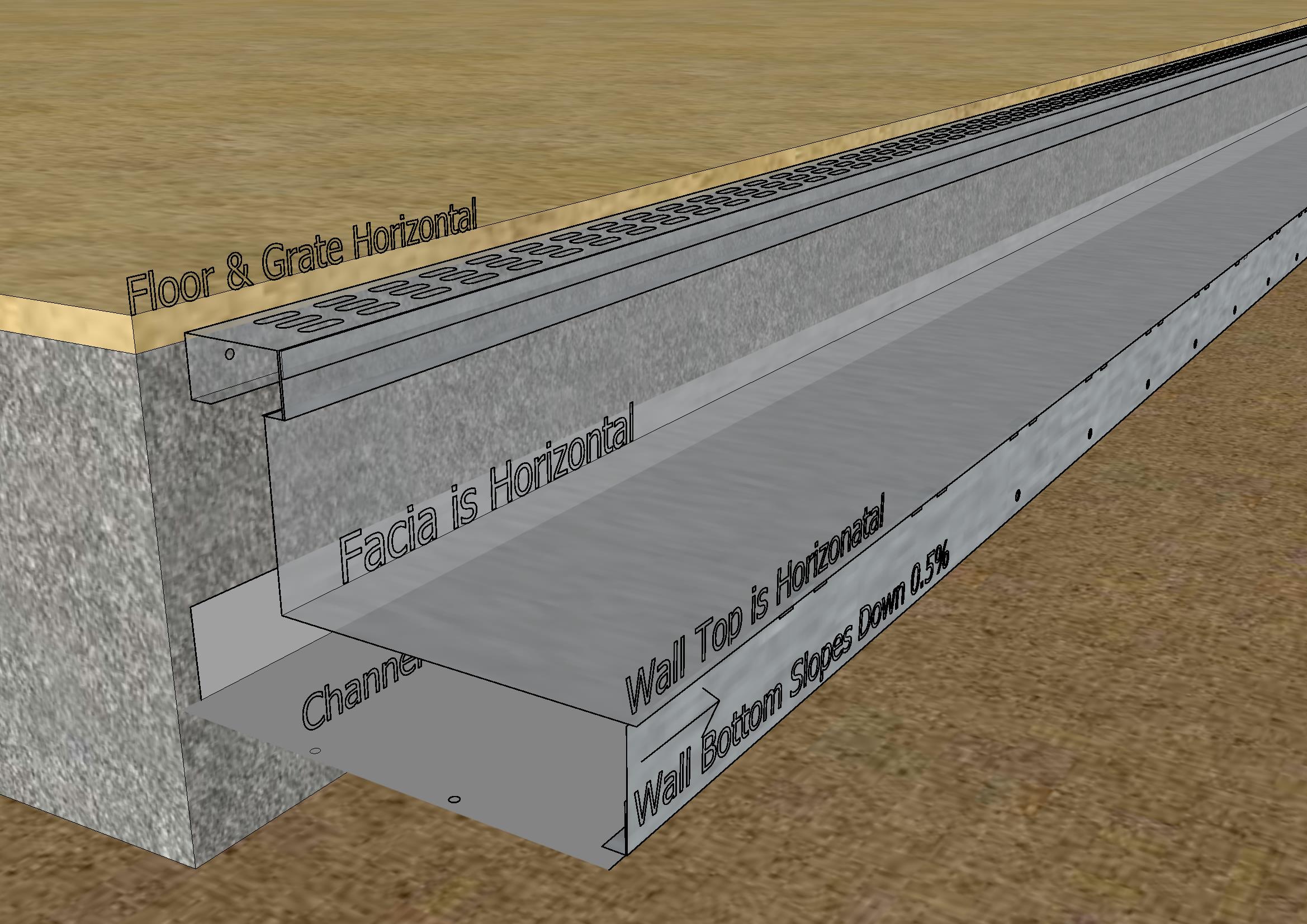
The Wall can be Rotated to Change Direction of Flow

The bottom of the Horizontal Section of the Fascia section is 102mm below the level of the Grating.
The Top of the Channel Wall is 102mm below the level of the Grating.

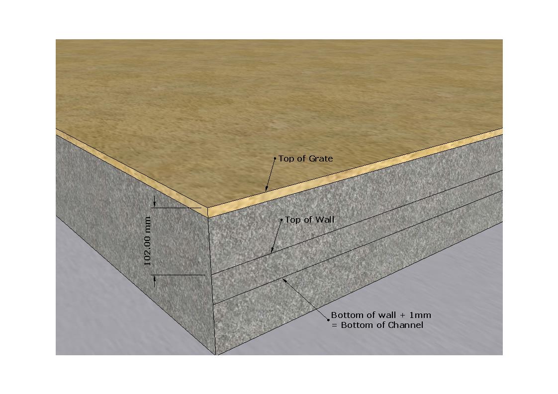
1st Step: Mark a "Stringline" on the face of the slab 102mm below the level of the Grating

2nd Step: After deciding on the direction of flow, use Wall as a template by aligning the top of the wall with the "Stringline" and then mark on slab the bottom of the wall.
The bottom line +1.00mm is the position of the bottom of the channel section.

There are now Two "Stringlines" marked on the slab face
Top Stringline: Top of Channel Wall
Bottom Stringline: Channel Base = Bottom of Channel Wall + 1mm (Sheet thinckness)
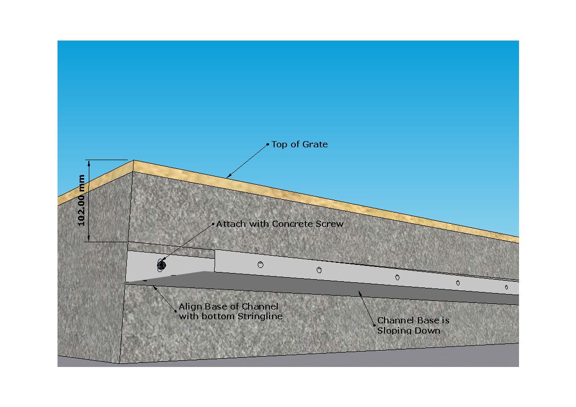
3rd Step: Attach the bottom of the Channal Base in line with the bottom stringline and attached to wall.
Concrete screws provided.
 4th Step : Attach Wall to Channel Base
5th Step: Attach Support Systems

6th Step: Attach Grating
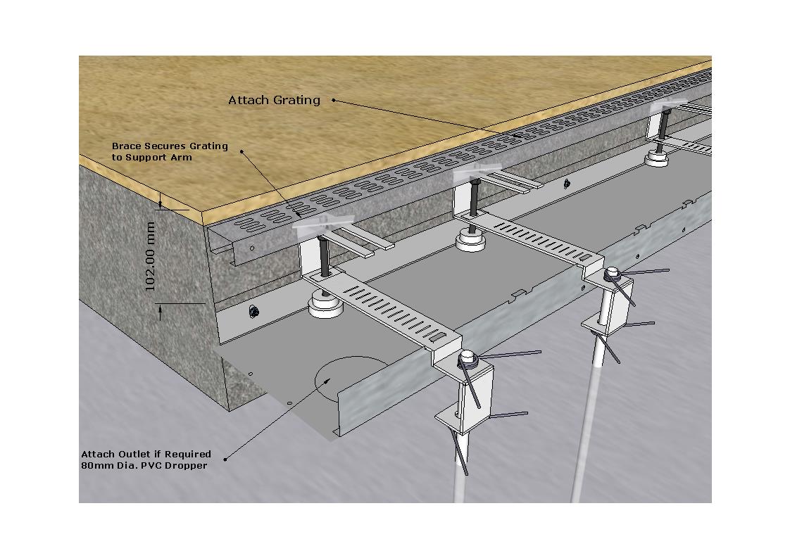
7th Step: Trim top of Support Arms
8th Step: Attach Outlet
Each three metre Channel Section has a 80mm diameter "knockout" which can be "punched out" for an outlet.
The following diagram and photos illustrate this feature. 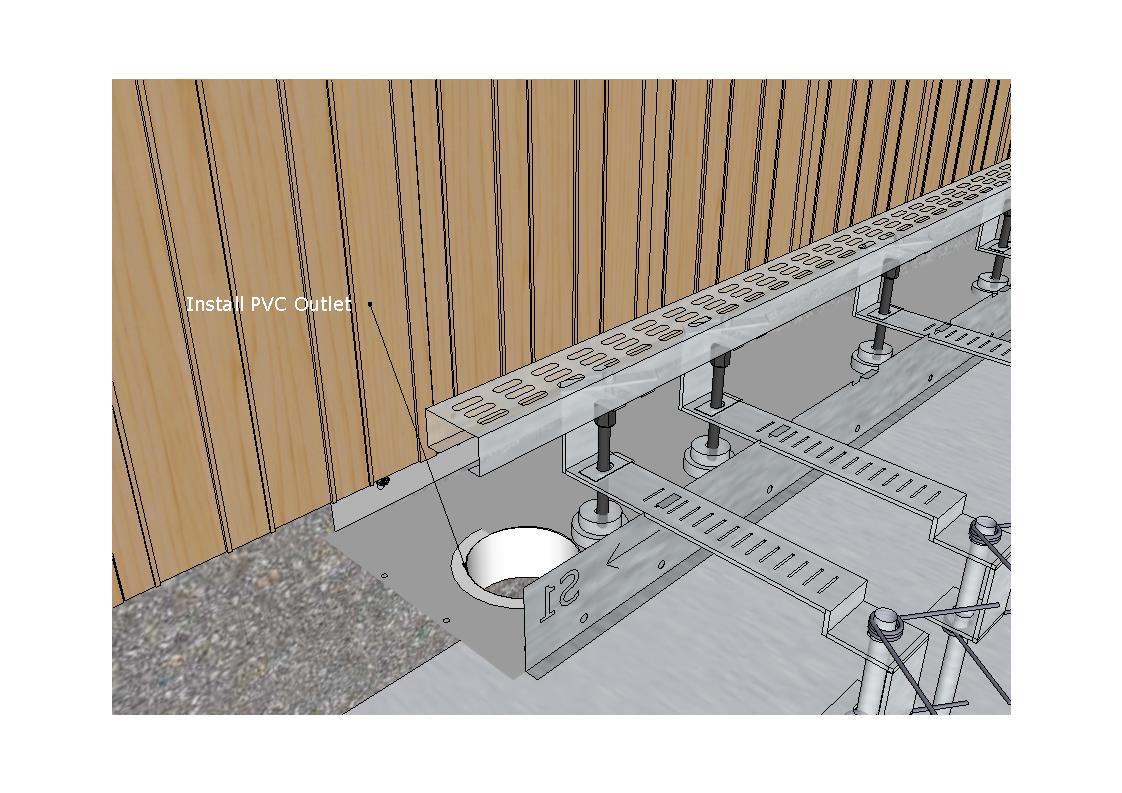
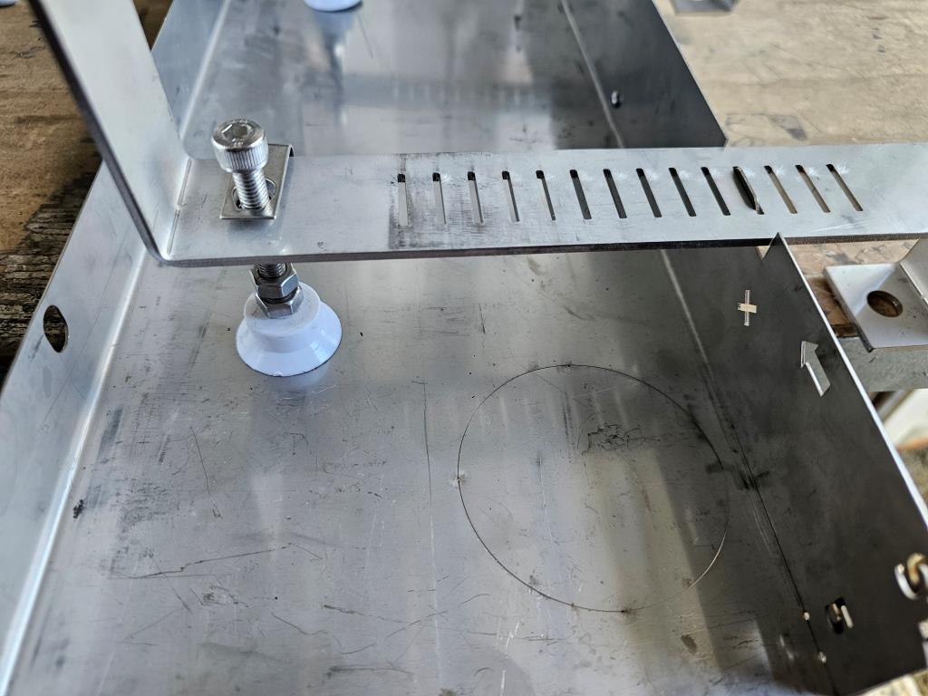
Knockout: The outlet hole is partial cut.
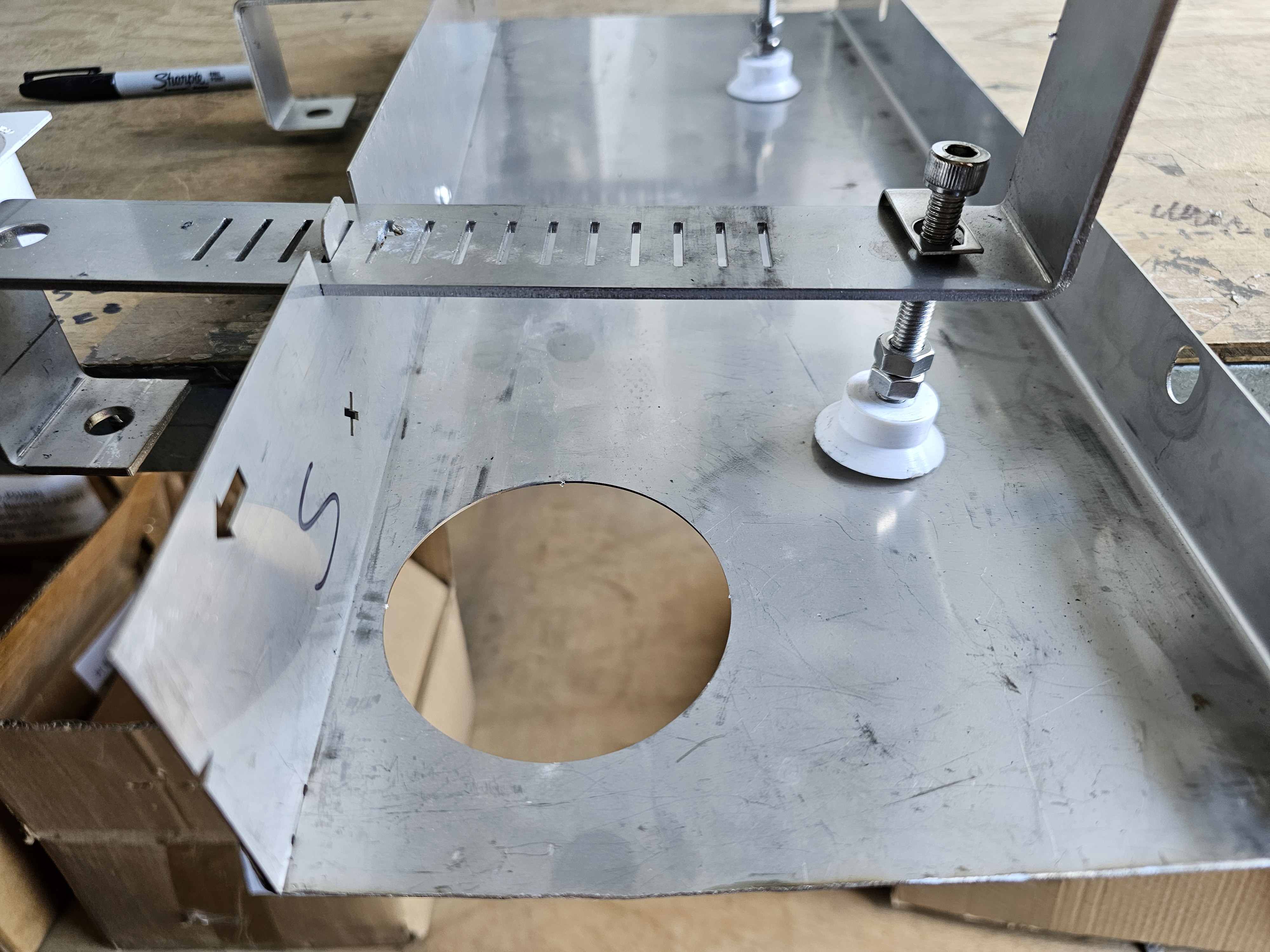
Knockout Removed: The knockout can be "punched out" with a swift hammer blow.
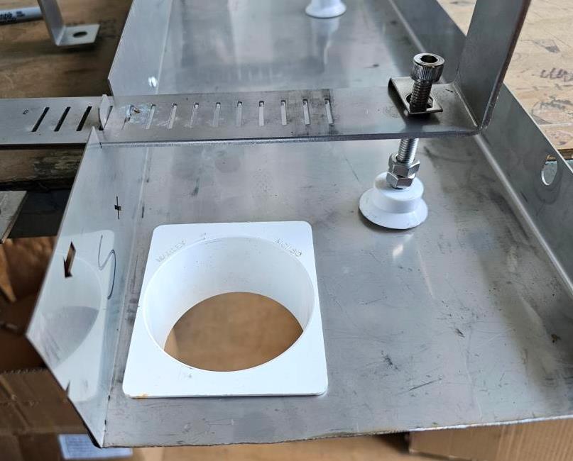
PVC Dropper (supplied) inserted into hole: Seal with a Silicon Sealant.
9th Step: Attached Fascia Section

10th Step: Attached End Cap or join to adjacent Channel ?
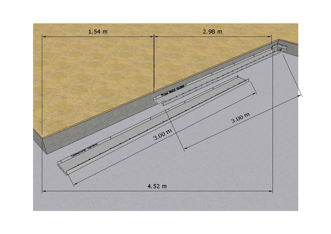
Telescopic Sections avoid the need to cut channel sections preceisly to fit.
The upstream telescopic section which is slightly narrower, "telescopes" into the adjacent downstream section.
The following diagrams illustrate this process spanning a 4.52m section.
Cut Telescopic section + ~100mm overlap

Insert Telescopic section into adjacent downstream section.
The wall of the downstream section is cut to fit.

Channel Sections are installed ready for other components to be attached.

In-Line Sumps
Outlet Side

Slab Side

Key Components

In-Line Sump Installation Process
Step 1: Install Bottom Section Against Slab with bottom adjacent Channel Sections on top of "inlet side" which has been folded down to a horizontal position.

Step 2: Install Fascia Section to butt up against side of sump

Step 3: Insert Top Section. The "Horizontal sides" will sit on top of the Fascia Section. These will need to be trimmed to fit.

Step 4. If required, fold top of bottom section side outward to fill gap.

Step 5: Insert Grates. The number of grates (45mm width) will depend on the offset distance from the slab.

Internal Corners
Top, Fascia Sections - Cut to Fit

Internal Corner, Installed

External Corners
Top, Fascia Sections - Cut to Fit


N.Z. Pat. Appl. No. 809326
Next: E2_Grating