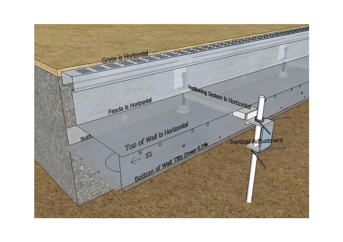
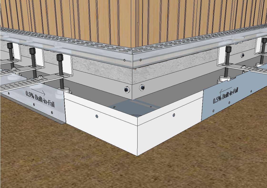
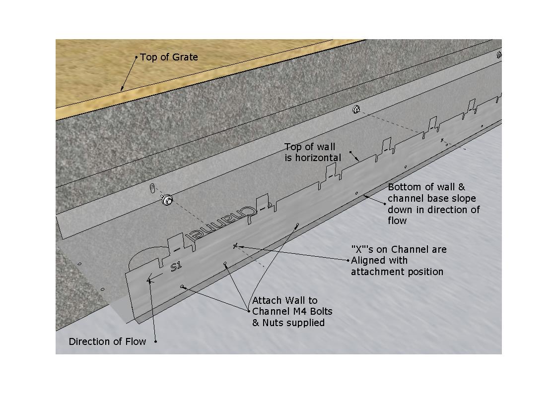
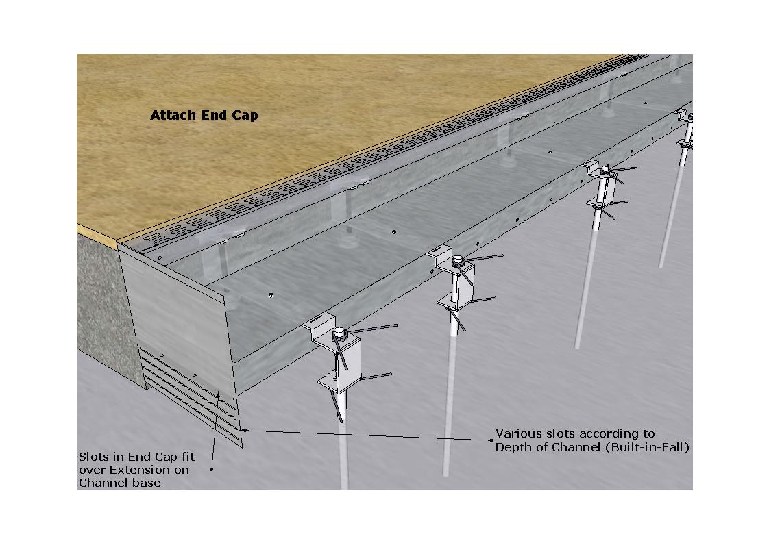
This following diagram illustrates the 1:200 (0.5%) Built-in-Fall is in the wall of the Channel
The Wall can be Rotated to Change Direction of Flow
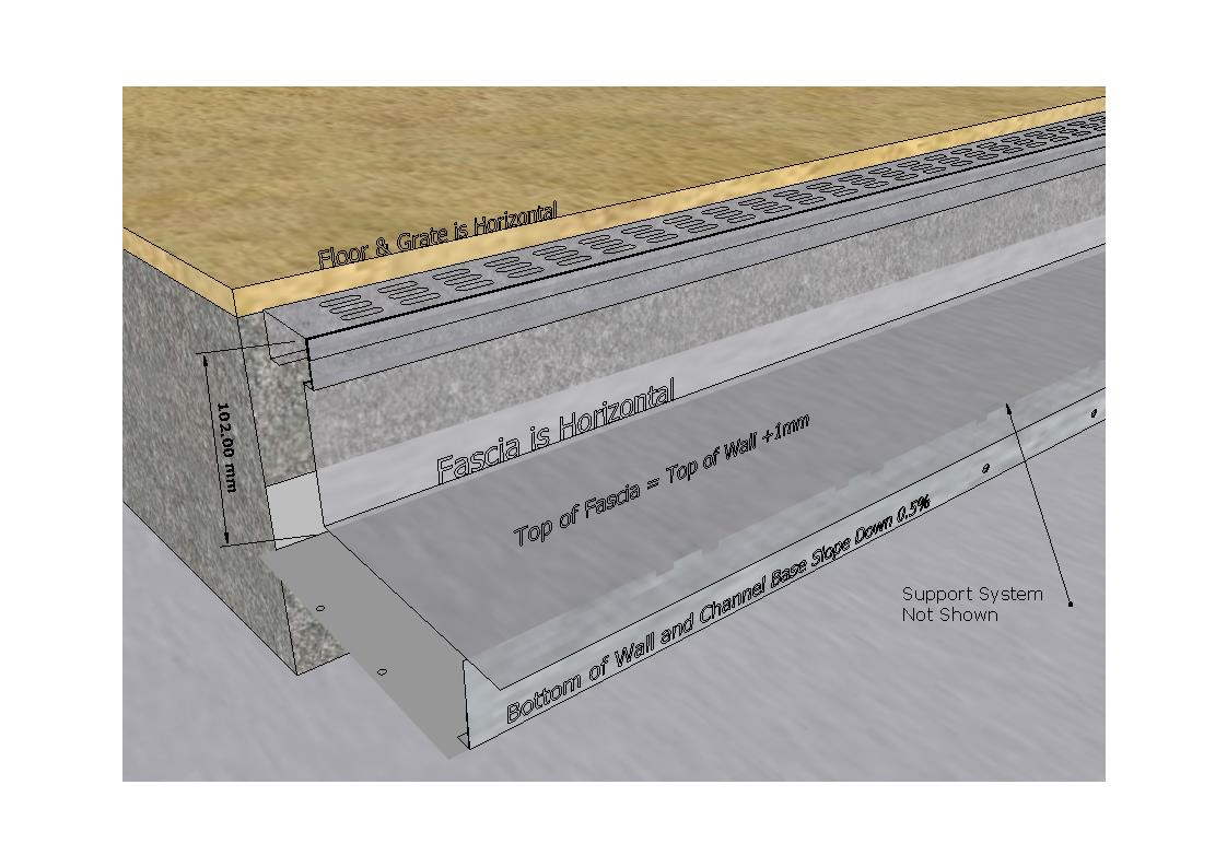
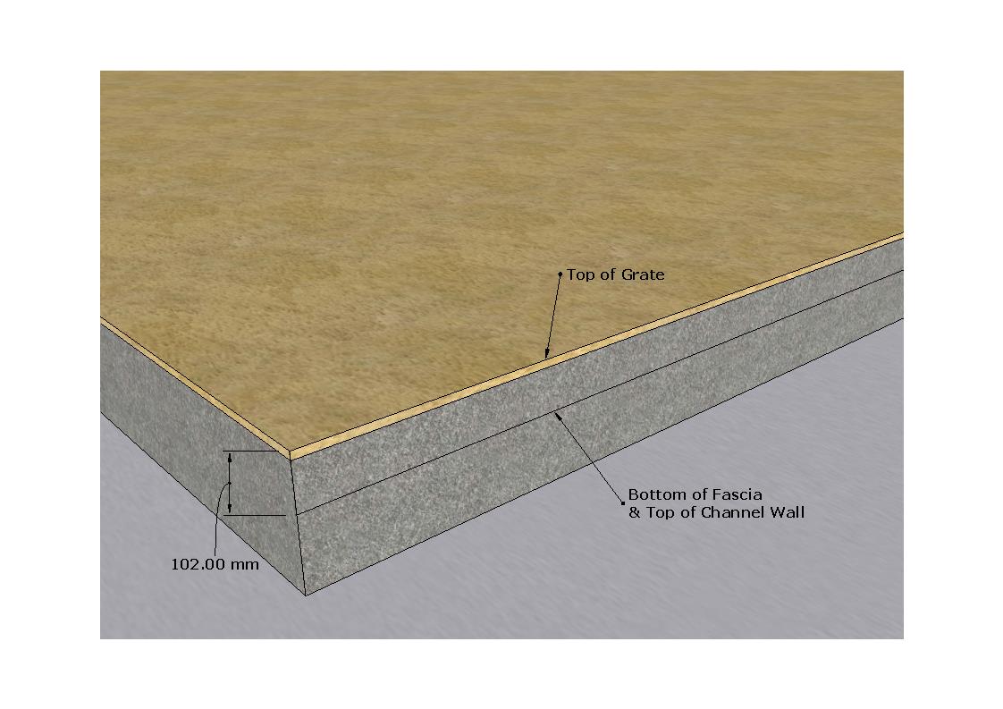
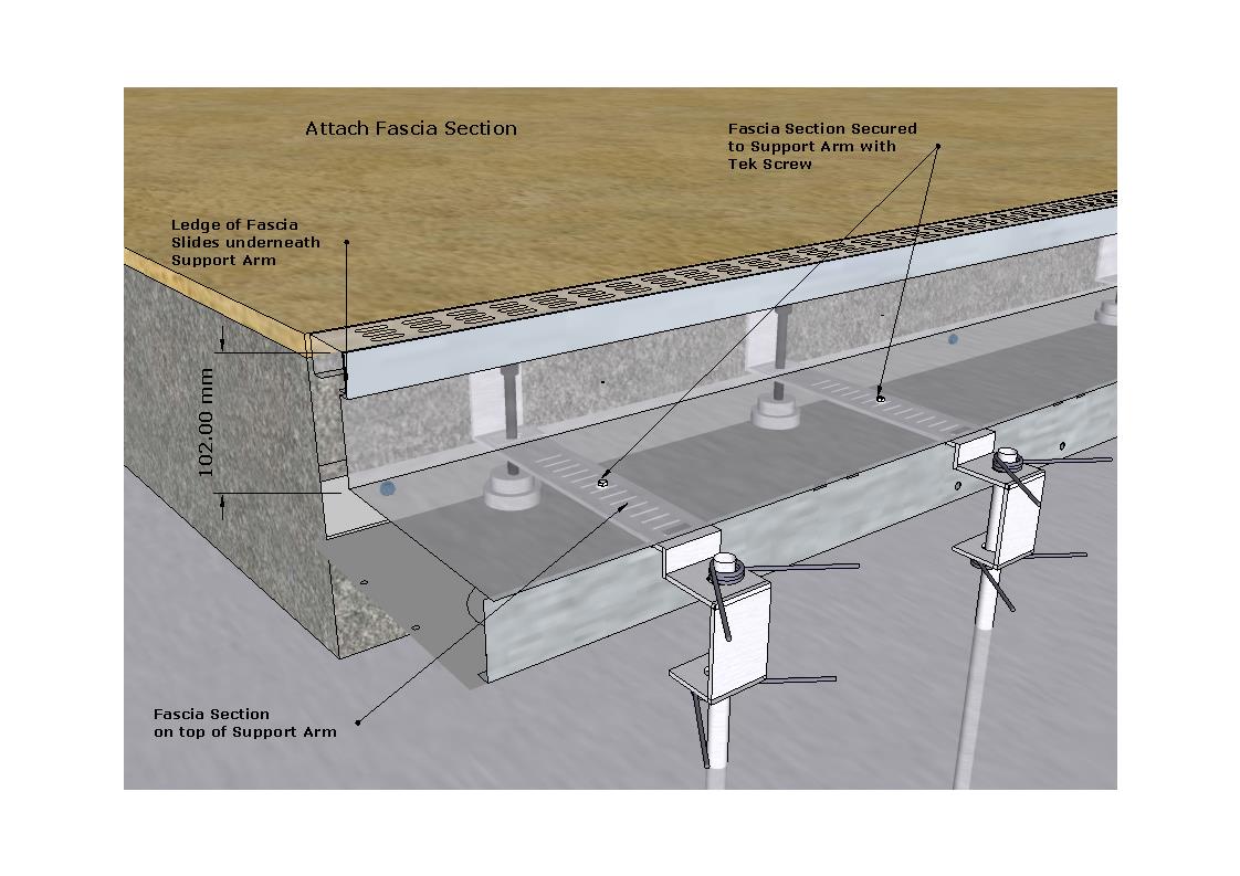
The bottom of the Horizontal Section of the Fascia section is 102mm below the level of the Grating.
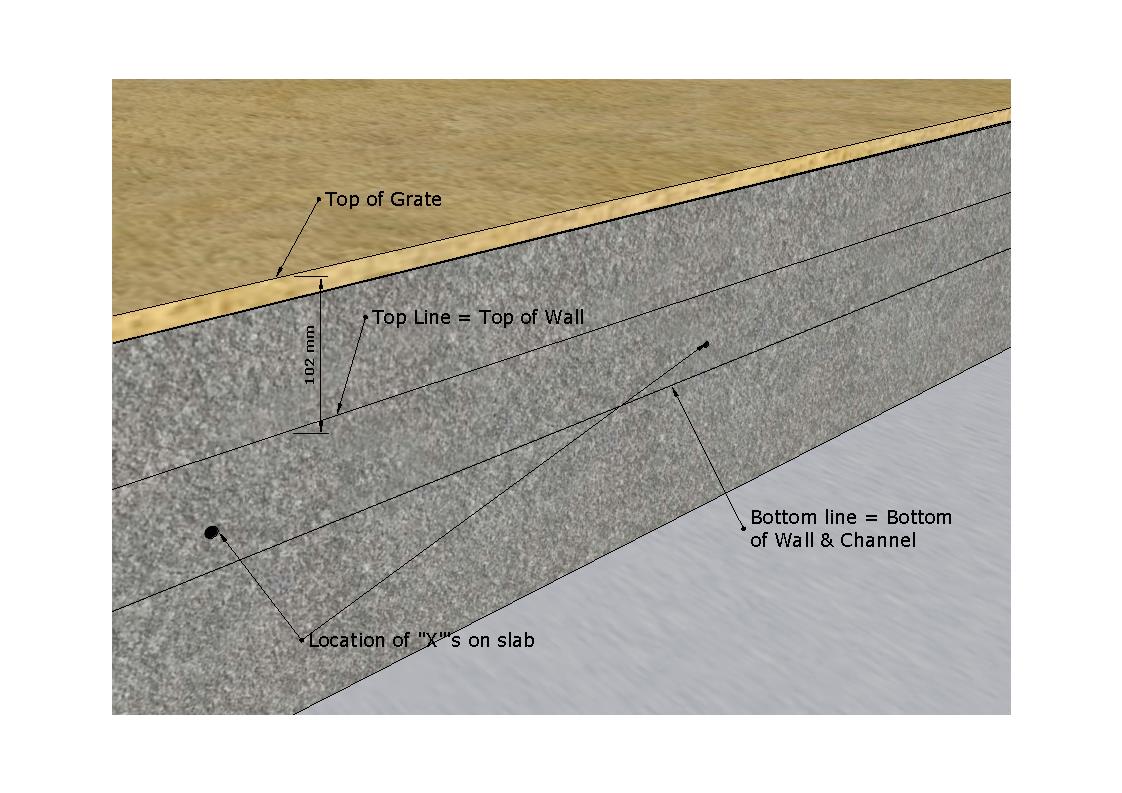
The Top of the Channel Wall is 102mm below the level of the Grating.
1st Step: Mark a "Stringline" on the face of the slab 102mm below the level of the Grating
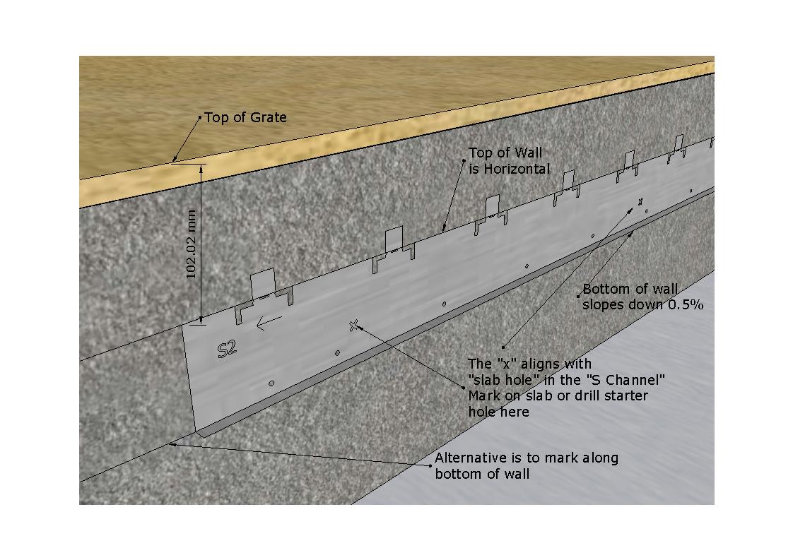
2nd Step: Use the Channel Wall as a Template
After deciding on the direction of flow, use the channel wall as a template by aligning the top of the wall with the "Stringline" and then mark on slab the at the "X's" or along the bottom of the wall.
The bottom line +1.00mm is the position of the bottom of the channel section.
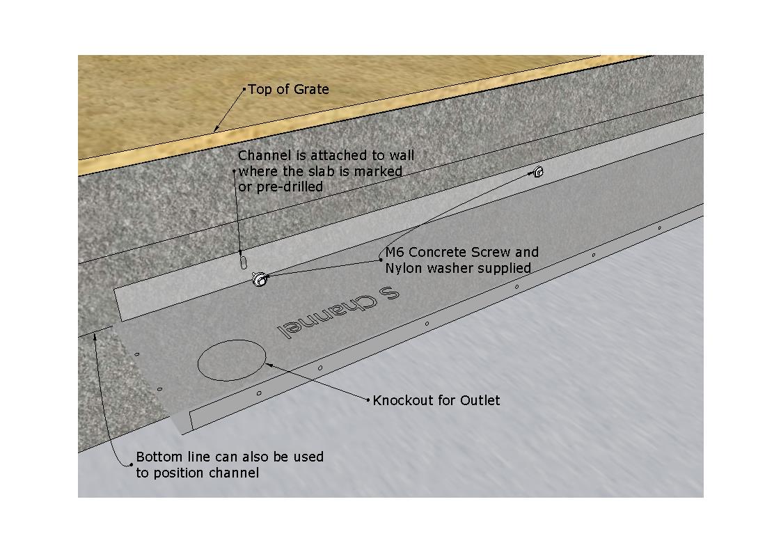
The location of where to attach the channel base is marked (or drilled) on the slab face.
3rd Step: Attach the bottom of the Channal Base in line with the bottom stringline and attached to wall.
Concrete screws provided.
4th Step : Attach Wall to Channel Base
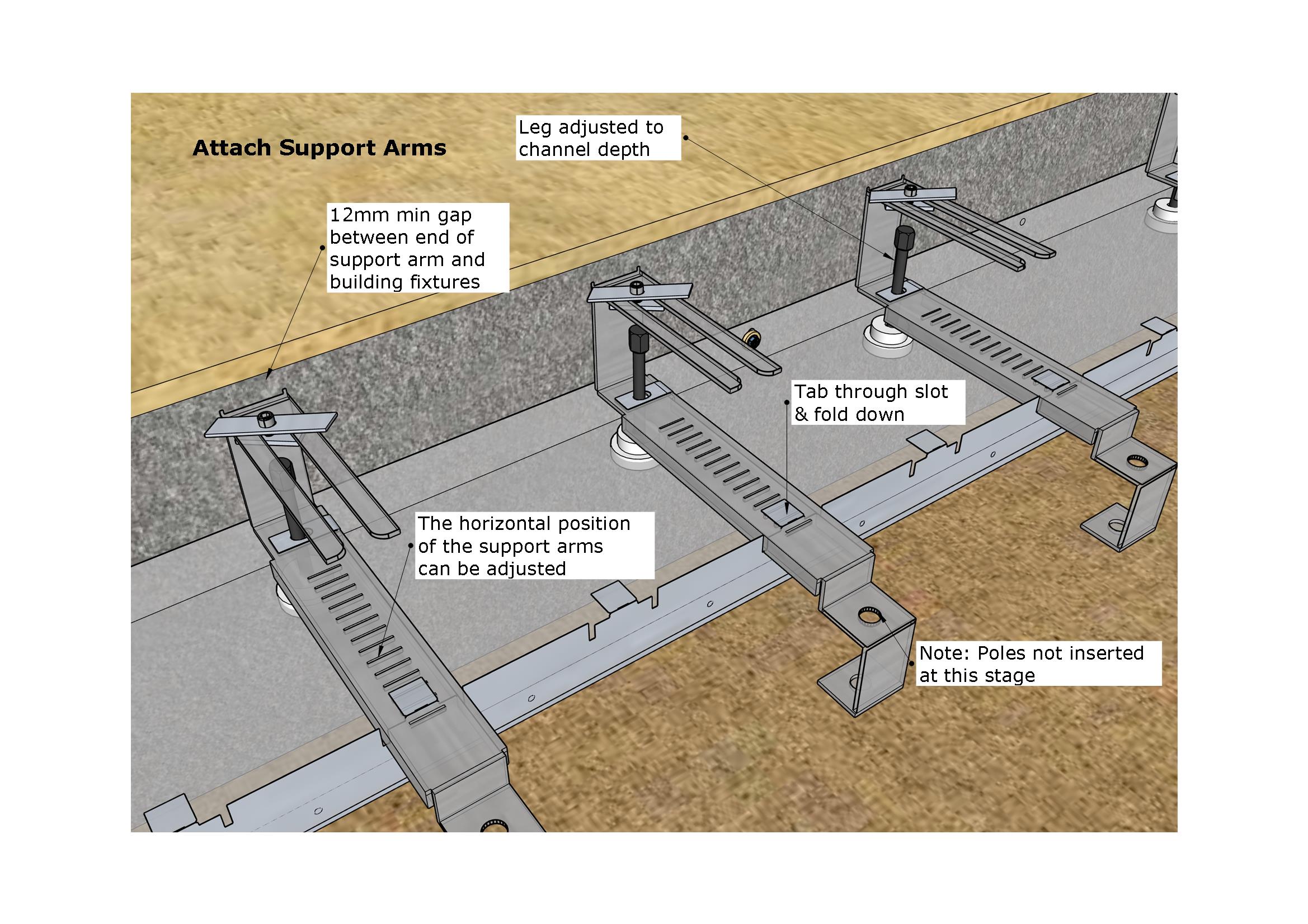
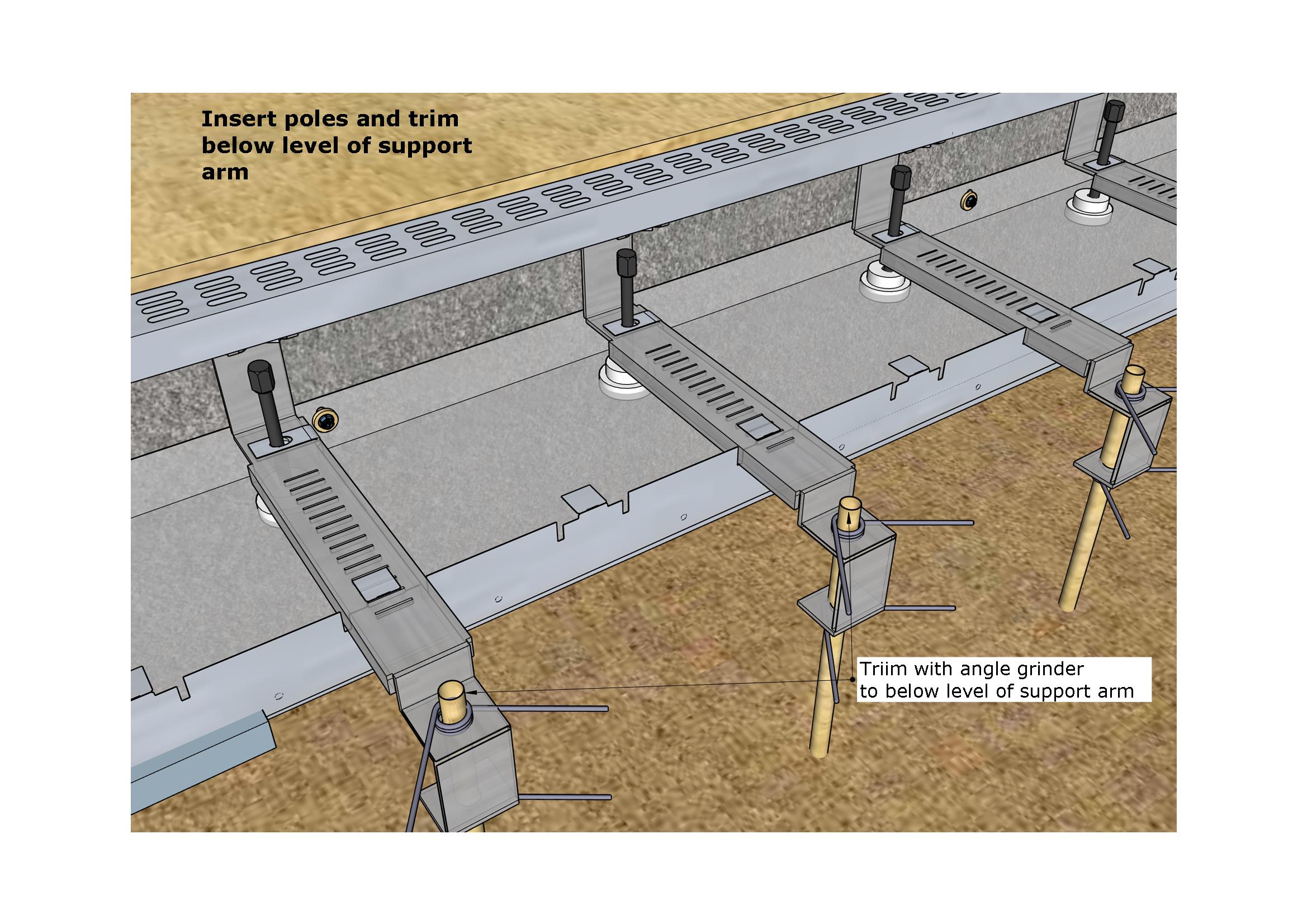
5th Step: Attach Support Arms
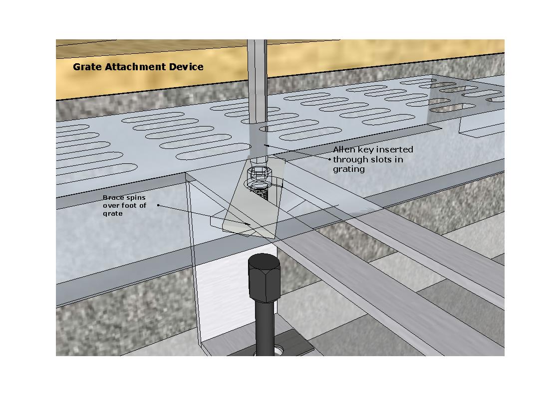
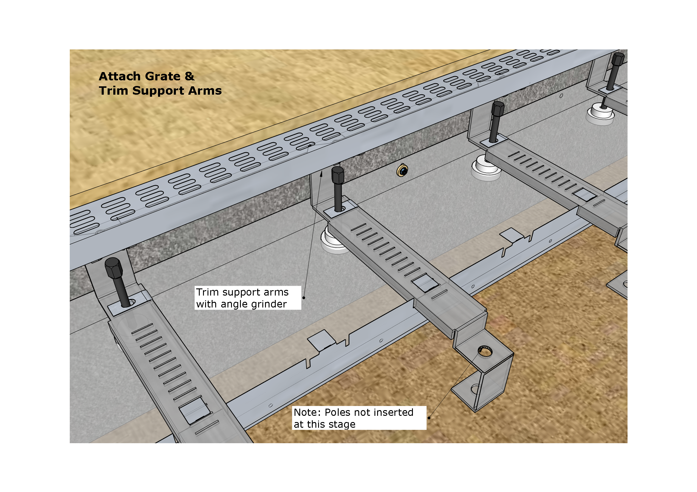
6th Step: Attach Grating and Trim Support Arms
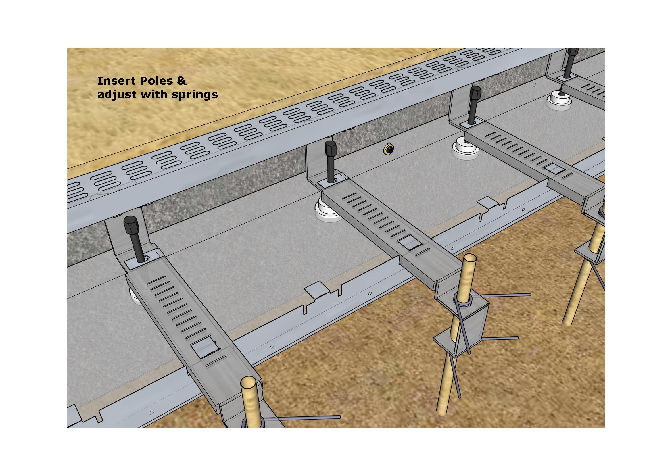
7th Step: Insert Poles and trim top
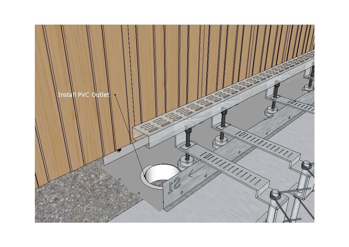
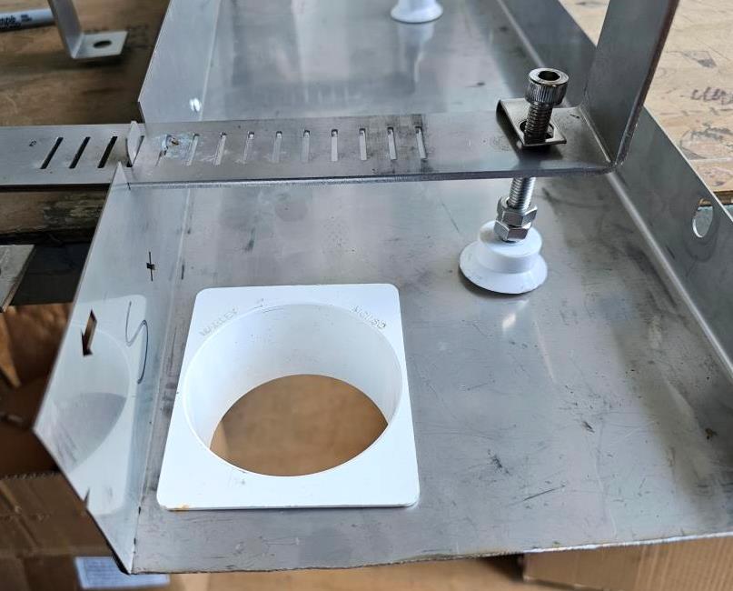
8th Step: Attach Outlet
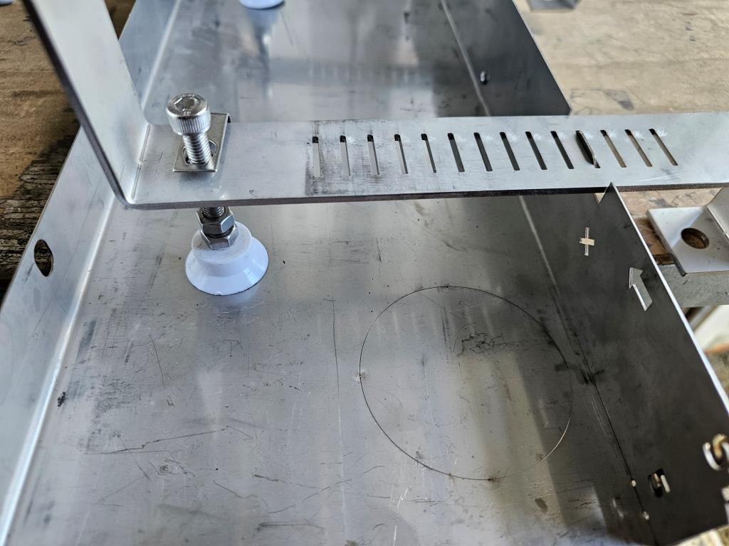
Each three metre Channel Section has a 80mm diameter "knockout" which can be "punched out" for an outlet.
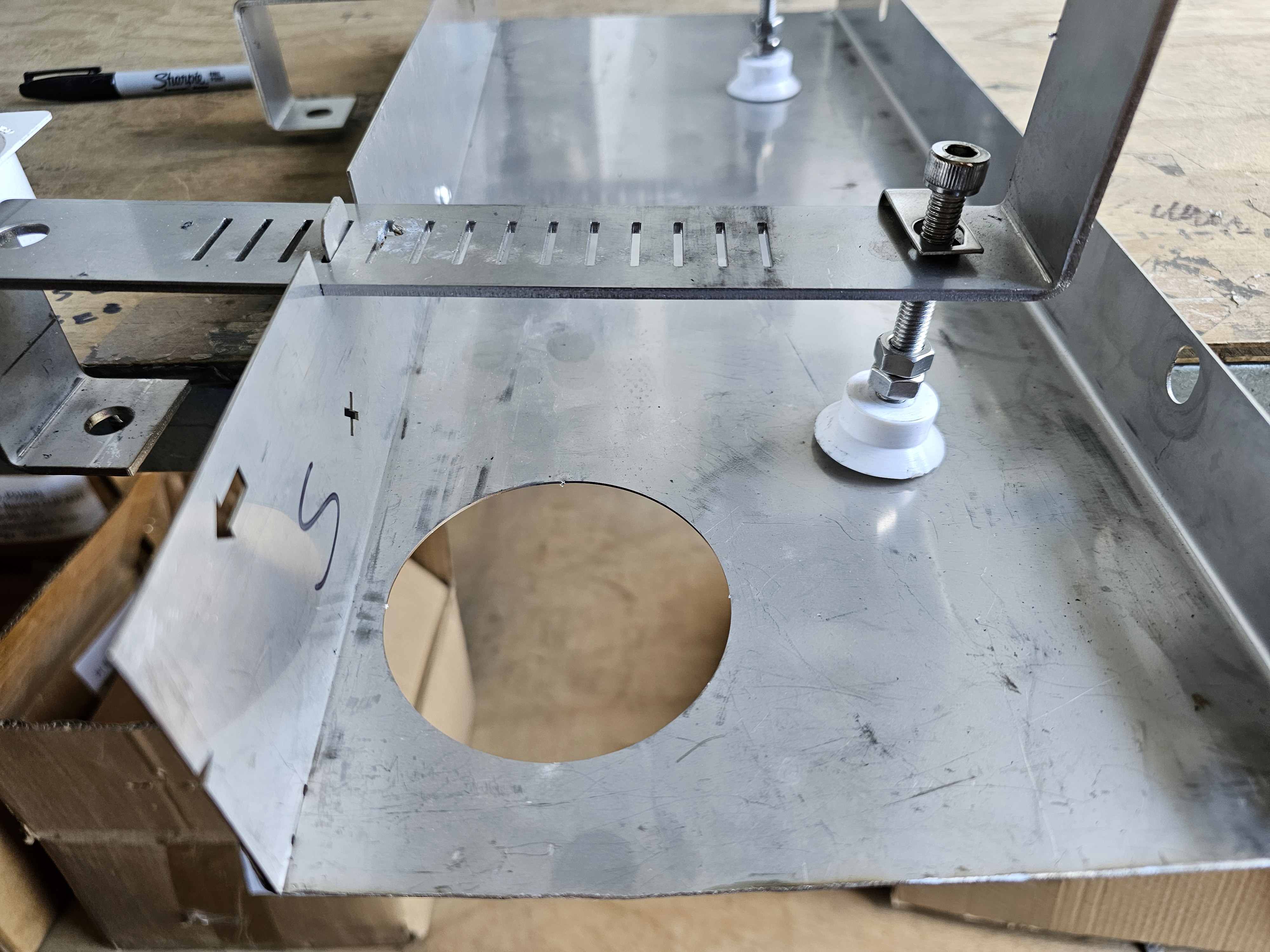
The following diagram and photos illustrate this feature.
Knockout: The outlet hole is partial cut.
Knockout Removed: The knockout can be "punched out" with a swift hammer blow.
PVC Dropper (supplied) inserted into hole: Seal with a Silicon Sealant.
9th Step: Attached Fascia Section
10th Step: Attached End Cap or Join to next Channel Section